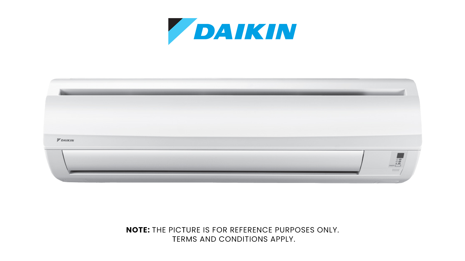
Air conditioner manufacturers often include error codes in their manual for user reference. If you no longer have the manual for your unit, check our
list below for the list of Daikin error codes by indoor or outdoor unit.
Indoor Unit Error Codes
| Error Code | Meaning |
|---|---|
| A0 | The external protection device is activated, connected to the terminal strip. |
| A1 | Malfunctioning Printed Circuit Board (PCB) – indoor unit. |
| A3 | Drain Level Control System Abnormality. |
| A4 | Malfunction of the freeze-protection feature. |
| A5 | High pressure control in heating; freeze-up protection control in cooling |
| A6 | Malfunctioning fan motor. |
| A7 | Malfunctioning swing flap motor |
| A8 | Malfunction in the power supply, or AC input overcurrent. |
| A9 | Malfunction in the electronic expansion valve. |
| AA | Heater is overheating. |
| AF | Malfunctioning humidifier system. |
| AH | Malfunction of the dust collector in the air cleaner. |
| AJ | Malfunction of the capacity setting – indoor unit Printed Circuit Board (PCB). |
| C1 | Failure of transmission – between indoor unit PCB and sub PCB. |
| C4 | Malfunctioning liquid pipe thermistor for heat exchanger. |
| C5 | Malfunctioning gas pipe thermistor for heat exchanger. |
| C6 | Malfunctioning fan motor sensor or fan control driver. |
| C7 | Faulty front panel driving motor. |
| C9 | Malfunction in the suction air thermistor. |
| CA | Malfunction in the discharge air thermistor. |
| CC | Malfunctioning humidity sensor system. |
| CJ | Abnormality in the room temperature thermistor of the remote controller. |
Outdoor Unit Error Codes
| Error Code | Meaning |
|---|---|
| E0 | Protection devices activated. |
| E1 | Defective Printed Circuit Board (PCB) – outdoor unit. |
| E3 | Actuation of High Pressure Switch (HPS). |
| E4 | Actuation of Low Pressure Switch (LPS). |
| E5 | Inverter compressor motor overheating. |
| E6 | STD compressor motor overcurrent/lock. |
| E7 | Malfunctioning outdoor unit fan motor system. |
| E8 | Overcurrent of inverter compressor. |
| E9 | Malfunctioning electronic expansion valve coil. |
| EA | Malfunctioning four way valve or cool/heat switch. |
| EC | Malfunction in the entering water temperature. |
| F3 | Malfunction in discharge pipe temperature. |
| F6 | Abnormal high pressure or refrigerant overcharged. |
| H0 | Malfunctioning sensor system of compressor. |
| H1 | Malfunctioning room temperature sensor or humidifier unit damper. |
| H3 | Malfunctioning high pressure switch (HPS). |
| H4 | Malfunctioning low pressure switch (LPS). |
| H5 | Malfunctioning compressor motor overload thermistor. |
| H6 | Malfunctioning position detection sensor. |
| H7 | Malfunctioning outdoor unit fan motor signal. |
| H8 | Malfunctioning compressor input (CT) system. |
| H9 | Malfunctioning outdoor air thermistor. |
| HC | Malfunctioning hot water temperature thermistor. |
| HF | Alarm in thermal storage unit or storage controller. |
| HJ | Malfunctioning thermal storage tank water level. |
| J1 | Malfunctioning pressure sensor. |
| J2 | Malfunctioning current sensor of compressor. |
| J3 | Malfunction in the discharge pipe thermistor. |
| J4 | Malfunction of the low pressure equivalent saturated temperature sensor system. |
| J5 | Malfunction in the suction pipe thermistor |
| J6 | Malfunction in the heat exchanger thermistor. |
| J7/J8/J9 | Malfunction in the thermistor – refrigerant circuit. |
| JA/JC | Malfunctioning high pressure sensor. |
| JE | Malfunctioning oil pressure sensor or sub-tank thermistor. |
| JF | Malfunctioning oil level sensor or heating heat exchanger thermistor. |
| L0 | Malfunction of the inverter system. |
| L1 | Malfunction of inverter PCB. |
| L3 | EL. COMPO. Box temperature rise. |
| L4 | Malfunction of inverter radiation temperature rise. |
| L5 | Inverter instantaneous overcurrent – DC output. |
| L6 | Inverter instantaneous overcurrent – AC output. |
| L8 | Malfunction of overcurrent inverter compressor. |
| L9 | Malfunction of inverter compressor startup error. |
| LA | Malfunction of power transistor. |
| LC | Malfunction of connection between control and inverter PCB. |
| M1 | Malfunction of central remote controller PCB. |
| M8 | Malfunction of connection between optional controllers for centralized control. |
| MA | Improper combination of optional controllers for centralized control. |
| MC | Address duplication; improper setting. |
| P0 | Shortage of refrigerant amount in the thermal storage unit. |
| P1 | Power voltage imbalance or inverter PCB. |
| P2 | Automatic refrigerant charge operation stop. |
| P3 | Malfunction of thermistor in switch box. |
| P4 | Malfunction of radiation temperature sensor. |
| P8 | Heat exchanger freezing protection during automatic refrigerant charging. |
| P9 | Malfunction of fan motor in the humidifier unit. |
| P9 | Automatic refrigerant charge operation completed. |
| PA | Refrigerant cylinder during automatic refrigerant charging. |
| PA | Broken wire of heater in the humidifier unit. |
| PC | Refrigerant cylinder during automatic refrigerant charging. |
| PE | Automatic refrigerant charge operation nearly completed. |
| PH | Refrigerant cylinder during automatic refrigerant charging. |
| PJ | Malfunction of capacity setting (Outdoor unit PCB). |
| PJ | Malfunction of transmission between inverter and fan driver. |


